The purpose of this experiment is to obtain a graph of piston velocity against crank angle using the method of instantaneous centers, assuming that the crank rotates at a constant angular velocity and to obtain the crank angles which correspond to the maximum piston velocity. Then, to show that for a slider crank chain the piston motion tends to approach simple harmonic motion with increasing values of connecting rod/crank ratio. The apparatus used is the Slider Crank Chain with a variable connecting rod length mechanism apparatus, shown in the Appendix section. With reference to the theory of the experiment, the result is obtained by rotate the crank by 10° increments and note the corresponding piston displacement and the cross-scale readings for five different connecting rod lengths: 115, 130, 140, 155 and 175 mm. This step is repeated for a full 360° rotation. The result of the experiment is tabulated and shown at the Data, Observation and Result section. The graph of piston displacement and velocity against the crank angle for the five connecting rod is plotted in one graph in FIGURE 1 and FIGURE 2. Below are the findings of the experiment:
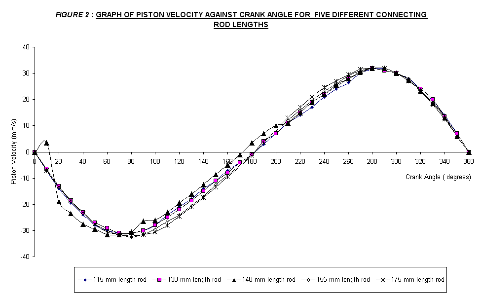
· The relationship between the piston velocity against the crank angle has a sinusoidal characteristic.
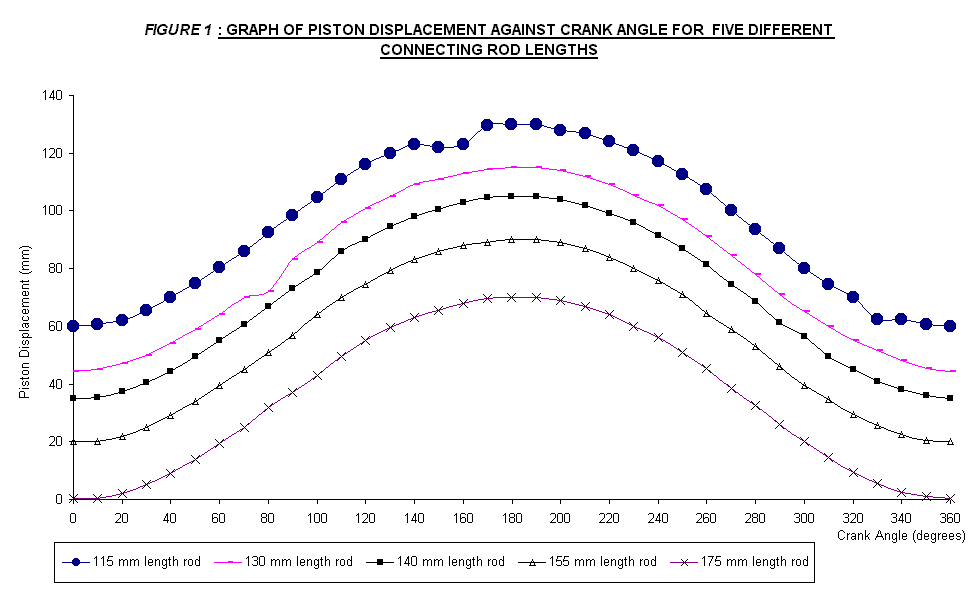
· The piston displacement against crank angle shows a quadratic characteristic.
· But, the two common characteristic from both figures are both the piston displacement and velocity will go back to its initial condition after completing one revolution cycle.
· For different connecting rod lengths, the ratio between connecting rod and crank radius is different. Consequently, the point of maximum displacement will also different.
· The higher the ratio, the lower the maximum point of its displacement.
· Maximum piston velocity for all the graph that were plotted occur at an angle of 80° and 280° instead of 90° and 270° as stated as the theoretical value.
· The piston was under simple harmonic motion due to the fact that it was under the oscillating motion. It has a maximum acceleration due to the increasing and decreasing of the piston velocity of the mechanism itself.
· It is found that the maximum acceleration is about 0.3 mm/s2 and it occurred at an angle about 250° to 260°.
·
The maximum acceleration and the maximum velocity do not occur at the
same crank angle. At the angle
where the maximum velocity occurs, the acceleration must have a value of zero.
In conclusion, by using the method
of instantaneous centers, the piston velocity is obtained and it is proved that
the piston motion tends to approach simple harmonic motion with the increasing
values of the corresponding rod/crank ratio. The experiment results showed that
it tends to agree to the theoretical part of experiment.
The purpose of this experiment is to obtain a graph of piston velocity against crank angle using the method of instantaneous centers, assuming that the crank rotates at a constant angular velocity and to obtain the crank angles which correspond to the maximum piston velocity. Then, finally to show that for a slider crank chain the piston motion tends to approach simple harmonic motion with increasing values of connecting rod/crank ratio.
2. Both knurled nuts are slacken and adjust the position of the piston pivot so that the connecting rod is 115 mm long. Make sure that the spacer washer is between the piston and the connecting rod. In normal use, the knurled nuts will be just slack. However, the motion of the slider crank chain can be locked at any position by tightening both knurled nuts.
3. Record the piston displacement and the cross-scale readings in table for every 10° of crank rotation. Note that with the crank angle set to zero, note the initial reading of the cross-scale. This will need subtracting from all subsequent readings in order to obtain the true reading.
4. Steps 1 to 3 are repeated for connecting rod lengths of 130, 140, 155 and 175 mm.
Data,
Observation and Result
The
data for the piston displacement and piston velocity for the five different
connecting rod lengths were shown in tables below.
Ø
Table
1:
|
Connecting
rod length : |
115
mm |
|
|
|
Crank
radius: |
35
mm |
|
|
|
Ratio
: |
3.3 |
|
|
|
|
|
|
|
|
Crank
angle |
Piston
Displacement |
Piston
Velocity |
|
|
(degrees) |
(mm) |
(mm/s) |
|
|
0 |
60.0 |
0.0 |
|
|
10 |
60.5 |
-7.0 |
|
|
20 |
62.0 |
-14.0 |
|
|
30 |
65.5 |
-19.5 |
|
|
40 |
70.0 |
-24.0 |
|
|
50 |
75.0 |
-28.0 |
|
|
60 |
80.5 |
-30.0 |
|
|
70 |
86.0 |
-31.0 |
|
|
80 |
92.5 |
-31.0 |
|
|
90 |
98.5 |
-30.0 |
|
|
100 |
104.5 |
-28.0 |
|
|
110 |
111.0 |
-24.0 |
|
|
120 |
116.0 |
-21.0 |
|
|
130 |
120.0 |
-18.0 |
|
|
140 |
123.0 |
-14.0 |
|
|
150 |
122.0 |
-11.0 |
|
|
160 |
123.0 |
-7.0 |
|
|
170 |
129.5 |
-4.0 |
|
|
180 |
130.0 |
-1.0 |
|
|
190 |
130.0 |
3.0 |
|
|
200 |
128.0 |
7.0 |
|
|
210 |
127.0 |
11.0 |
|
|
220 |
124.0 |
14.0 |
|
|
230 |
121.0 |
17.0 |
|
|
240 |
117.0 |
21.0 |
|
|
250 |
112.5 |
24.0 |
|
|
260 |
107.5 |
26.5 |
|
|
270 |
100.0 |
30.0 |
|
|
280 |
93.5 |
31.5 |
|
|
290 |
87.0 |
32.0 |
|
|
300 |
80.0 |
30.0 |
|
|
310 |
74.5 |
28.0 |
|
|
320 |
70.0 |
24.0 |
|
|
330 |
62.5 |
19.5 |
|
|
340 |
62.5 |
14.0 |
|
|
350 |
60.5 |
7.0 |
|
|
360 |
60.0 |
0.0 |
|
Ø
Table
2:
|
Connecting
rod length : |
130
mm |
|
|
Crank
radius: |
35
mm |
|
|
Ratio
: |
3.7 |
|
|
|
|
|
|
Crank
angle |
Piston
Displacement |
Piston
Velocity |
|
(degrees) |
(mm) |
(mm/s) |
|
0 |
44.5 |
0.0 |
|
10 |
45.0 |
-6.5 |
|
20 |
47.0 |
-13.0 |
|
30 |
50.0 |
-18.5 |
|
40 |
54.0 |
-23.0 |
|
50 |
59.0 |
-27.0 |
|
60 |
64.0 |
-29.0 |
|
70 |
70.0 |
-31.0 |
|
80 |
72.0 |
-31.0 |
|
90 |
83.0 |
-30.0 |
|
100 |
89.0 |
-28.0 |
|
110 |
96.0 |
-25.0 |
|
120 |
101.0 |
-22.0 |
|
130 |
105.0 |
-18.5 |
|
140 |
109.0 |
-15.0 |
|
150 |
111.0 |
-11.0 |
|
160 |
113.0 |
-8.0 |
|
170 |
114.5 |
-4.0 |
|
180 |
115.0 |
-1.0 |
|
190 |
115.0 |
4.0 |
|
200 |
114.0 |
7.0 |
|
210 |
112.0 |
11.0 |
|
220 |
109.0 |
15.0 |
|
230 |
105.5 |
19.0 |
|
240 |
102.0 |
22.0 |
|
250 |
97.0 |
25.0 |
|
260 |
91.0 |
28.0 |
|
270 |
84.5 |
30.0 |
|
280 |
78.0 |
32.0 |
|
290 |
71.0 |
31.0 |
|
300 |
65.0 |
30.0 |
|
310 |
60.0 |
27.0 |
|
320 |
55.0 |
24.0 |
|
330 |
51.5 |
20.0 |
|
340 |
48.0 |
13.5 |
|
350 |
45.5 |
7.0 |
|
360 |
44.5 |
0.0 |
Ø
Table
3:
|
Connecting
rod length : |
140
mm |
|
|
Crank
radius: |
35
mm |
|
|
Ratio
: |
4.0 |
|
|
|
|
|
|
Crank
angle |
Piston
Displacement |
Piston
Velocity |
|
(degrees) |
(mm) |
(mm/s) |
|
0 |
35.0 |
0.0 |
|
10 |
35.5 |
3.5 |
|
20 |
37.5 |
-19.0 |
|
30 |
40.5 |
-23.5 |
|
40 |
44.5 |
-27.5 |
|
50 |
49.5 |
-29.5 |
|
60 |
55.0 |
-31.5 |
|
70 |
60.5 |
-31.5 |
|
80 |
67.0 |
-30.5 |
|
90 |
73.0 |
-26.5 |
|
100 |
78.5 |
-26.0 |
|
110 |
86.0 |
-23.0 |
|
120 |
90.0 |
-19.5 |
|
130 |
94.5 |
-16.0 |
|
140 |
98.0 |
-12.5 |
|
150 |
100.5 |
-8.5 |
|
160 |
103.0 |
-5.0 |
|
170 |
104.5 |
-1.0 |
|
180 |
105.0 |
3.5 |
|
190 |
105.0 |
7.0 |
|
200 |
104.0 |
10.0 |
|
210 |
102.0 |
11.0 |
|
220 |
99.0 |
15.0 |
|
230 |
96.0 |
19.0 |
|
240 |
91.5 |
22.0 |
|
250 |
87.0 |
25.5 |
|
260 |
81.5 |
28.0 |
|
270 |
74.5 |
30.5 |
|
280 |
68.5 |
32.0 |
|
290 |
61.5 |
32.0 |
|
300 |
56.5 |
30.0 |
|
310 |
49.5 |
27.5 |
|
320 |
45.0 |
23.0 |
|
330 |
41.0 |
18.5 |
|
340 |
38.0 |
13.0 |
|
350 |
36.0 |
6.0 |
|
360 |
35.0 |
0.0 |
Ø
Table
4:
|
Connecting
rod length : |
155
mm |
|
|
Crank
radius: |
35
mm |
|
|
Ratio
: |
4.4 |
|
|
|
|
|
|
Crank
angle |
Piston
Displacement |
Piston
Velocity |
|
(degrees) |
(mm) |
(mm/s) |
|
0 |
20.0 |
0.0 |
|
10 |
20.0 |
-7.0 |
|
20 |
22.0 |
-13.5 |
|
30 |
25.0 |
-19.0 |
|
40 |
29.0 |
-23.5 |
|
50 |
34.0 |
-27.5 |
|
60 |
39.5 |
-30.0 |
|
70 |
45.0 |
-31.5 |
|
80 |
51.0 |
-32.5 |
|
90 |
57.0 |
-31.5 |
|
100 |
64.0 |
-29.5 |
|
110 |
70.0 |
-26.5 |
|
120 |
74.5 |
-24.0 |
|
130 |
79.5 |
-20.5 |
|
140 |
83.0 |
-17.0 |
|
150 |
86.0 |
-12.5 |
|
160 |
88.0 |
-9.0 |
|
170 |
89.0 |
-5.0 |
|
180 |
90.0 |
-1.0 |
|
190 |
90.0 |
4.0 |
|
200 |
89.0 |
8.0 |
|
210 |
87.0 |
12.0 |
|
220 |
84.0 |
16.0 |
|
230 |
80.0 |
19.5 |
|
240 |
76.0 |
23.0 |
|
250 |
71.0 |
26.0 |
|
260 |
64.5 |
29.0 |
|
270 |
59.0 |
31.0 |
|
280 |
53.0 |
32.0 |
|
290 |
46.0 |
32.0 |
|
300 |
39.5 |
30.0 |
|
310 |
34.5 |
28.0 |
|
320 |
29.5 |
23.5 |
|
330 |
25.5 |
19.0 |
|
340 |
22.5 |
13.5 |
|
350 |
20.5 |
6.0 |
|
360 |
20.0 |
0.0 |
Ø
Table
5:
|
Connecting
rod length : |
175
mm |
|
|
Crank
radius: |
35
mm |
|
|
Ratio
: |
5.0 |
|
|
|
|
|
|
Crank
angle |
Piston
Displacement |
Piston
Velocity |
|
(degrees) |
(mm) |
(mm/s) |
|
0 |
0.5 |
0.0 |
|
10 |
0.5 |
-7.0 |
|
20 |
2.0 |
-13.5 |
|
30 |
5.3 |
-18.5 |
|
40 |
9.0 |
-23.5 |
|
50 |
14.0 |
-27.5 |
|
60 |
19.5 |
-30.5 |
|
70 |
25.0 |
-31.5 |
|
80 |
32.0 |
-32.0 |
|
90 |
37.0 |
-31.5 |
|
100 |
43.0 |
-30.5 |
|
110 |
49.5 |
-28.0 |
|
120 |
55.0 |
-24.5 |
|
130 |
59.5 |
-21.0 |
|
140 |
63.0 |
-17.5 |
|
150 |
65.5 |
-13.5 |
|
160 |
68.0 |
-9.5 |
|
170 |
69.5 |
-5.5 |
|
180 |
70.0 |
-1.5 |
|
190 |
70.0 |
3.5 |
|
200 |
69.0 |
8.5 |
|
210 |
67.0 |
13.0 |
|
220 |
64.0 |
17.0 |
|
230 |
60.0 |
21.0 |
|
240 |
56.0 |
24.5 |
|
250 |
51.0 |
27.0 |
|
260 |
45.5 |
29.5 |
|
270 |
38.5 |
31.5 |
|
280 |
32.5 |
32.0 |
|
290 |
26.0 |
32.0 |
|
300 |
20.0 |
30.0 |
|
310 |
14.5 |
27.0 |
|
320 |
9.5 |
23.5 |
|
330 |
5.5 |
18.0 |
|
340 |
2.5 |
12.5 |
|
350 |
1.0 |
6.0 |
|
360 |
0.5 |
0.0 |
From the data recorded, the graph of piston displacement and piston velocity against crank angle for the five different connecting rod lengths was plotted in one graph shown in FIGURE 1 and FIGURE 2, attached next page.
Discussion
From
the experimental data tabulated and the plotted graphs in FIGURE 1 and FIGURE2,
the relationship between the piston displacement and velocity against the
crank angle is obtained. From
FIGURE 2, it is clearly that the graph has a sinusoidal characteristic.
On the other hand, FIGURE 1 shows a quadratic characteristic.
But, the two common characteristic from both figures are both the piston
displacement and velocity will go back to its initial condition after completing
one revolution. For different
connecting rod lengths, the ratio between connecting rod and crank radius is
different. Consequently, the point
of maximum displacement will also different.
The higher the ratio, the lower the maximum point of its displacement.
The experiment results showed that it tends to agree to the theoretical
part of experiment. With reference
to FIGURE 2, it can be clearly seen that the graph has a sinusoidal
characteristic. But, there was not
much different for five connecting rods in terms of their maximum and minimum
velocity. The slight difference or
error occurred might be due to the inefficiency of the apparatus itself.
Maximum
piston velocity for all the graph that were plotted occur at an angle of 80°
and 280°
instead of 90°
and 270°
as stated as the theoretical value. This
showed that the error occurred in experiment has contributes the 10°
difference. Although there exist
difference, it can be said that the experiment results tend to agree quite well
with the theory.
The
piston was under simple harmonic motion due to the fact that it was under the
oscillating motion. It has a
maximum acceleration due to the increasing and decreasing of the piston velocity
of the mechanism itself. The higher
the value of the ratio would give a better shape and form of simple harmonic
motion of the plotted graph. The
maximum acceleration occurs at the steepest slope among the plotted graph in
FIGURE 2. Based on it, it is quite hard to find by just looking at the
graphs. So, finding the best
steepest slope of the plotted graphs will make an assumption. It is found that the maximum acceleration is about 0.3 mm/s2
and it occurred at an angle about 250°
to 260°.
The maximum acceleration and the maximum velocity do not occur at the
same crank angle. The simple
relationship is obtained. At the
angle where the maximum velocity occurs, the acceleration must have a value of
zero.
Conclusion