The purpose of this experiment is to investigate the motion of a slotted link and to see if the piston rod moves with Simple Harmonic Motion. The apparatus used is the Slotted Link Mechanism apparatus, shown in APPENDIX.
The result of the experiment is tabulated and shown at the Data, Observation and Result section. The graph of both experimental and theoretical piston rod displacement against angle was plotted in one graph. The theoretical piston rod velocity and acceleration is also plotted. Below are the findings of the experiment based on the results and the plotted graphs.
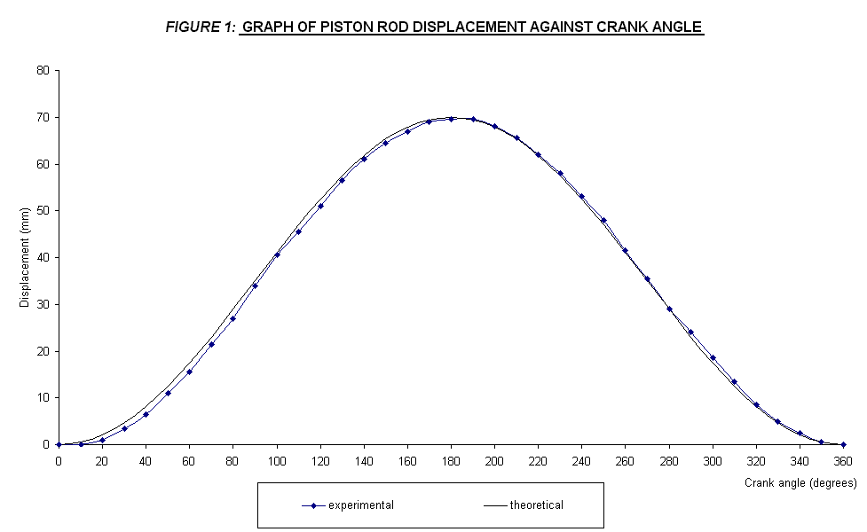
1. With reference to the experimental data tabulated and the plotted graph, the theoretical and measured values of piston rod displacement shows a small deviation. The maximum displacement is about 69.5 mm experimentally compared to 70 mm theoretically. Both is at an angle of 180°.
2. The average percentage of error is about 8.46 %. This may be caused by the error that occur while performing the experiment
3. Piston rod displacement, velocity, acceleration and force is in sinuusoidal behaviour and Simple Harmonic Motion. This is proven by the behaviour of the plotted graphs.
4.
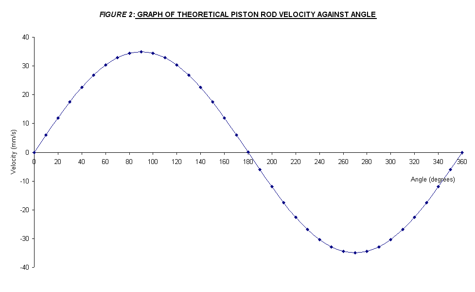
The maximum velocity on the drive pin was at 90°
and 270 but in different direction. The
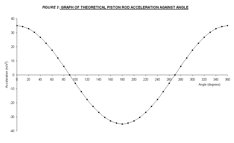
maximum acceleration and force of the drive pin also accur at 180°
same as the maximum displacement point and at an angle of 0°
and 360°.
These acceleration is same in magnitude but in different direction.
In
conclusion, by doing the slotted link mechanism experiment, motion of a slotted
link has been investigated. The
results is tend to agree with theoretical results.
Therefore, the objective of the experiment is achieved since the results
of the experiment has revealed that the motion of slotted link and the piston
rod moves with Simple Harmonic Motion since the aceleration was proportional to the displacement.
Purpose
/ Objective
The purpose of this experiment is to investigate the motion of a slotted link and to see if the piston rod moves with Simple Harmonic Motion.
Procedure
1. The crank was set to 0° and the piston displacement was recorded.
2. The crank was moved by 10° and the displacement is again recorded.
3. Repeat step 1 and 2 for one complete revolution of the crank.
4. The theoretical piston displacement was also calculated.
The
data of the experimantal and theoretical piston rod displacement corresponding
to angle of crank rotation is shown in TABLE
1 below.
|
Crank
angle, q |
Experimental
piston rod |
Theoretical |
Error |
|
(degrees) |
displacement,
x (mm) |
displacement
(mm) |
(%) |
|
0 |
0 |
0 |
0 |
|
10 |
0 |
0.53 |
100 |
|
20 |
1 |
2.11 |
52.62 |
|
30 |
3.5 |
4.69 |
25.36 |
|
40 |
6.5 |
8.19 |
20.62 |
|
50 |
11 |
12.50 |
12.02 |
|
60 |
15.5 |
17.50 |
11.43 |
|
70 |
21.5 |
23.03 |
6.64 |
|
80 |
27 |
28.92 |
6.65 |
|
90 |
34 |
35 |
2.86 |
|
100 |
40.5 |
41.08 |
1.41 |
|
110 |
45.5 |
46.97 |
3.13 |
|
120 |
51 |
52.50 |
2.86 |
|
130 |
56.5 |
57.50 |
1.73 |
|
140 |
61 |
61.81 |
1.31 |
|
150 |
64.5 |
65.31 |
1.24 |
|
160 |
67 |
67.89 |
1.31 |
|
170 |
69 |
69.47 |
0.67 |
|
180 |
69.5 |
70 |
0.71 |
|
190 |
69.5 |
69.47 |
0.05 |
|
200 |
68 |
67.89 |
0.16 |
|
210 |
65.5 |
65.31 |
0.29 |
|
220 |
62 |
61.81 |
0.30 |
|
230 |
58 |
57.50 |
0.87 |
|
240 |
53 |
52.50 |
0.95 |
|
250 |
48 |
46.97 |
2.19 |
|
260 |
41.5 |
41.08 |
1.03 |
|
270 |
35.5 |
35 |
1.43 |
|
280 |
29 |
28.92 |
0.27 |
|
290 |
24 |
23.03 |
4.22 |
|
300 |
18.5 |
17.50 |
5.71 |
|
310 |
13.5 |
12.50 |
7.98 |
|
320 |
8.5 |
8.19 |
3.80 |
|
330 |
5 |
4.69 |
6.63 |
|
340 |
2.5 |
2.11 |
18.44 |
|
350 |
0.5 |
0.53 |
5.97 |
|
360 |
0 |
0 |
0 |
TABLE
1
·
Average percentage of
error = 8.46 %
From the data recorded, the graph of measured and theoretical piston rod displacement against crank angle is plotted in one graph, shown in FIGURE 1, attached in the APPENDIX.
Discussion
With reference to the experimental data tabulated and the plotted graph, the theoretical and measured values of piston rod displacement shows a small deviation. The average percentage of error is about 8.46 %. This may be caused by the error that occurs while performing the experiment. One possible source of error is due to parallax error. Parallax error happens when taking the displacement reading from the apparatus has lead to the loss of accuracy and precision of the experiment results. But, these difference does not effect so much in order to achieve the experiment objective. By looking at the pattern and behavior of the plotted graph, it can be said that the piston rod moved sinusoidally and Simple Harmonic Motion. The maximum displacement is about 69.5 mm experimentally compared to 70 mm theoretically. Both is at an angle of 180°. After reaching maximum at 180°, the piston will moved back to its initial position at 0 mm at 360°. It can be said that the displacement is increased in the first 180° of travel, but decrease back to initial position at another 180°.
The
theoretical piston rod velocity and acceleration is calculated and is shown in Table
2, attached in the APPENDIX. Based
on these theoretical results, the graph of theoretical piston rod velocity and
acceleration instead of experimental velocity and acceleration against angle is
plotted. This is because the graph
of experimental velocity and acceleration seen to be distorted due to the error.
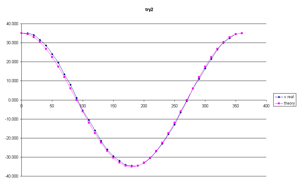
But, both theoretical and experimental plots will shows the same
behaviour that is Simple Harmonic Motion. The
two plotted graphs is shown in FIGURE 2
and FIGURE 3 attached in the APPENDIX. The maximum velocity on the drive pin was at 90° and 270°,
that is in the first and third quarter of the crank angle.
Since the velocity is a vector quantity, the maximum velocity is same in
magnitude but in opposite direction. The
maximum acceleration of the drive pin also accur at 180°
same as the maximum displacement point and at angle of 0°
and 360°,
which is the starting and ending point of crank rotation.
Consequently, this will make the maximum force on the drive pin occur
also at the same points since force is proportional to the acceleration. The force played an important role in transmitting the power
to the piston. The piston rod moves
horizontally and produced the displacement corresponding to the rotating crank
angle. Moreover, the aceleration
was also proportional to the displacement.
With reference to the SHM circle attached at the APPENDIX section, it is
clear that the driving pin which is fixed to the crank is similar to point Q on
the SHM circle. The piston rod with
a slotted link is constrained to move in a straight line.
The limits of motion is the end of a diameter of the circle of drive of
pin rotation. So, the motion of the
slotted link and piston rod are identical to point P in the SHM circle.
The theoretical formula and the sample of calculation of the piston rod
displacement, velocity and acceleration is shown in the APPENDIX.
In conclusion, by doing the slotted link mechanism experiment, motion of a slotted link has been investigated. The results of the experiment tends to agree to the theoretical aspects of the experiment. Although there is an error occur during performing the experiment, it does not effect the results of the experiment. Therefore, the objective of the experiment is achieved since the results of the experiment has revealed that the motion of slotted link and the piston rod moves with Simple Harmonic Motion.
Appendix
A.
General
equation:
Theoretical piston rod displacement, velocity and
acceleration calculation is based on the SHM circle below.
Q
is a point which rotates at constant velocity, w in a circle of radius . AB is
the diameter and O is the centre of the circle of rotation.
Point P is the projection of Q upon the diameter AB atbany instant.
The displacement of P from O is y. Clearly
point P oscillates between A and B as Q moves around the circle.
So, P can only have vlocities along AB at any instant in time, similarly
for accelerations.
It is clear
that the driving pin which is fixed to the crank is similar to point Q on the
SHM circle. The piston rod with a slotted link is constrained to move in
a straight line, x. The limits of
motion is the end of a diameter of the circle of drive of pin rotation.
So, the motion of the slotted link and piston rod are identical to point
P in the SHM circle.
Now, the acceleration is resolved into two components, parallel and
perpendicular to AB. As as result,
the parallel component will represent the acceleration of P. As Q moves along the SHM circle, piston rod displacement, x
will be equal to PB value. As a
result, the acceleration of P is proportional to its displacement, y.
Radius
of circle, R = r
OP
= y = r cos (wt)
= r cos q
\Theoretical
piston rod displacement, PB = x = r – y = r (1 – cos q)
--------------- (1)
\Theoretical
piston rod velocity = dx = dx =
r sin q
--------------- (2)
dt
dq
\Theoretical
piston rod acceleration = d2x
= r cos q
--------------- (3)
dq2
\Error
= (theoretical – experimental) / theoretical * 100%
----------------
(4)
B. Theoretical Sample of calculation:
R = 35 mm
q
= 20°
Radius
of circle, R = r
OP
= y = r cos (wt)
= r cos q
·
From equation (1) :
Theoretical
piston rod displacement, PB = x = r – y = r (1 – cos q)
= 35 (1-cos 20°)
=
2.11 mm
·
From
equation (2):
Theoretical
piston rod velocity = dx =
dx = r sin q
= 35 sin 20° = 11.97 mm/s
dt
dq
·
From
equation (3):
Theoretical
piston rod acceleration = d2x = r cos q
= 35 cos 20°
= 32.89 mm/s2
dq2
·
From equation (4):
Error
= (theoretical – experimental) / theoretical * 100%
At
q = 20°
\Error
= (2.11-1)/2.11*100 = 56.62%
C. Slotted link mechanism
D. Table of theoretical velocity and acceleration:
The
table below shows the theoretical piston rod velocity and acceleration.
|
Crank
angle |
Theoretical
|
Theoretical
|
|
(degrees) |
Velocity
(mm/s) |
Acceleration
(mm/s2) |
|
0 |
0.00 |
35.00 |
|
10 |
6.08 |
34.47 |
|
20 |
11.97 |
32.89 |
|
30 |
17.50 |
30.31 |
|
40 |
22.50 |
26.81 |
|
50 |
26.81 |
22.50 |
|
60 |
30.31 |
17.50 |
|
70 |
32.89 |
11.97 |
|
80 |
34.47 |
6.08 |
|
90 |
35.00 |
0.00 |
|
100 |
34.47 |
-6.08 |
|
110 |
32.89 |
-11.97 |
|
120 |
30.31 |
-17.50 |
|
130 |
26.81 |
-22.50 |
|
140 |
22.50 |
-26.81 |
|
150 |
17.50 |
-30.31 |
|
160 |
11.97 |
-32.89 |
|
170 |
6.08 |
-34.47 |
|
180 |
0.00 |
-35.00 |
|
190 |
-6.08 |
-34.47 |
|
200 |
-11.97 |
-32.89 |
|
210 |
-17.50 |
-30.31 |
|
220 |
-22.50 |
-26.81 |
|
230 |
-26.81 |
-22.50 |
|
240 |
-30.31 |
-17.50 |
|
250 |
-32.89 |
-11.97 |
|
260 |
-34.47 |
-6.08 |
|
270 |
-35.00 |
0.00 |
|
280 |
-34.47 |
6.08 |
|
290 |
-32.89 |
11.97 |
|
300 |
-30.31 |
17.50 |
|
310 |
-26.81 |
22.50 |
|
320 |
-22.50 |
26.81 |
|
330 |
-17.50 |
30.31 |
|
340 |
-11.97 |
32.89 |
|
350 |
-6.08 |
34.47 |
|
360 |
0.00 |
35.00 |
Table
2


